SPARE PARTS
- Stationary Crushers
- Grinding Mill
- Washing & Screening
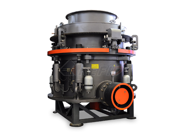
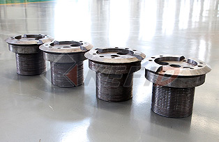
HPT Cone Crusher
HPT series high efficiency multiply cylinder hydraulic cone crusher has the advantages of high crushing capacity, low consumption, intelligent control and represent the most advanced cone crusher technology. HPT cone crusher is manily used in the secondary crushing and tertiary crushing. The main wearing parts including the mantle and concave wall.
-
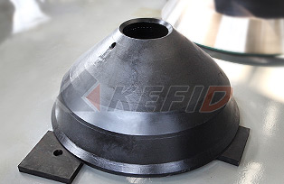
MANTLE
Material : ZGMn13-4
Function : mantle cover the cone body, concave wall fixed on the inside of adjusting ring, they are the main working part of the cone crusher. The feeding material go through the two parts and were broken by the mantle .
-
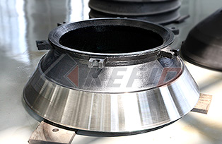
CONCAVE WALL
Material : ZGMn18
Function : Rolling mortar wall hanging beneath the adjustment ring, With the broken wall rotating extrusion material so as to achieve the suitable particle size.
-
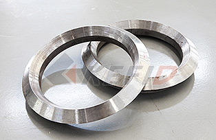
DOWN RING
Material : cast steel/Q235-A
Function : Down ring is used to lock the cone head, and functioned as a buffering and connection lock nut and the frame body.
-
LOCK NUT
Material : ZG270-500/ZG35SiMn
Function : Lock nut is at the very top, work as a screw nut, and to make sure the steadiness of the shaft and movable cone.
DISMANTLE THE CONCAVE WALL:
1. Dismantle the conehead, loosen the pressure cap and locking stud bolts on the top, this will make the pressure cap and cone loss of locking.
2. Using special wrench, tap wrench with a heavy sledgehammer rotate it clockwise to release the pressure cap.
3. Hanging the worn liner worn away from the cone.
4. Remove any residual filler material on the cone.
5. Check the pressure cap and cone thread, remove burrs or nicks that may exist and clean the threads thoroughly. Coated the threads with grease or oil.
6. Coat the moving cone and the outer surface of the cone adjustment ring surface with a thin layer of oil.
INSTALL THE MANTLE:
1. Smear a circle of dry oil around the lower contact surface of cone and liner plate before the mantle falling to the cone.
2. Down the liner plate on the cone. Put pressure ring at the top of the liner.
3. The pressure cap is screwed down to near the top of the pressure ring.
4. Hitting the wrench with a sledgehammer. Tighten the cap so that the liner on the moving cone is centring and in place.
5. After tightening the pressure cap onto the cone, tighten bolts cap on the top.
6. After cooling the liner, fill the cavity below the liner with filler.
CHANGE THE WORN CONCAVE WALL:
1. Dismantle the adjustment ring from the support sleeve.
2. Clean the support units, adjustment ring and locking nut threads thoroughly.
3. Lift to feed box from the adjustment ring.
4. Dismantle the cotter that is used to fix locking plate on the wedge, and then hanging out the locking plate.
5. Hanging the adjustment ring away from the liner.
6. Remove all packing traces on the adjustment ring.
INSTALL THE CONCAVE WALL:
1. Place the concave wall on the appropriate skids, ensuring complete contact after adjusting ring was put on the liner. Coat the adjustment ring inside lightly with oil.
2. Place the adjusting ring on the concave wall downward after installing the supporting ring in the adjusting ring.
3. Firstly, install each square head bolts, ball nuts and wedges.
4. Alternately screw up each nuts in symmetrically way, until all the wedges pressed into the bowl spiral line. Fill the padding into the filling cavity which is on the back of the concave wall.